-
Electronics Tutorial
Posted in: TutorialsTutorials explaining the basic concepts beginning electronics


-
-

-
Playlist Content
-

 1. Electronics Tutorial Introduction
This is the introduction to the basic electronics tutorial videos
Topics to be covered in the series:
* What is electricity, AC (alternating current), DC (direct current).
* Resistors, Ohms law, voltage, current
* Diodes, transistors, capacitors
* IC’s (integrated circuits), logic gates
* Practical demonstrations and analogies -
 2. Voltage, Current, Power, AC and DC
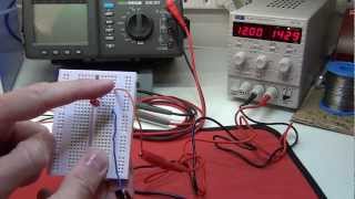
In this tutorial I cover the following:
* Some history about electricity / central power stations / electrification.
* Science of electron flow in a conductor / wire
* I use fluid dynamics in a pipe to explain voltage (pressure), current in Amps (flow) and consumption in Amp hours (rate of flow).
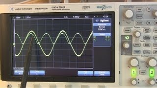
* We look at AC (alternating current) and DC (direct current) on the UNI-T UT81B scopemeter
* We look at how voltage / pressure is required to charge a 12 volt battery
* What is electricity? / How does electricity work?Nikola Tesla – http://en.wikipedia.org/wiki/Nikola_T…
Thomas Edison – http://en.wikipedia.org/wiki/Thomas_E… -
 3. Power - the relationship with Voltage and Current
In this tutorial I cover the following:
* Power – the relationship with Voltage and Current
* Power in watts = Volts x Amps (P=VI)Topics for future videos in this series:
* Ohms law, resistance, power, energy
* Electronic components – diodes, transistors, FETS, capacitors, digital logic gates, integrated circuits, 555 timer.
* Series and parallel circuits
* Op amps and feedback -
 4. Power Consumption & Battery Capacity
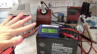
In this tutorial I cover the following:
* Power – the relationship with Voltage and Current
* Power in watts = Volts x Amps (P=VI)
* Power consumption in Wh = Power (Watts) x Time (hours)
* Current consumption in Ah = Curent (Amps) x Time (hours)
* Battery capacity
* More energy / power efficient circuits
* power consumption for BATTERIESTopics for future videos in this series:
* Ohms law, resistance, power, energy
* Electronic components – diodes, transistors, FETS, capacitors, digital logic gates, integrated circuits, 555 timer.
* Series and parallel circuits
* Op amps and feedbackWiki link: http://en.wikipedia.org/wiki/Electric…
-
 5. Ohm's Law I - Relationship between Current, Voltage and Resistance
Ohm’s law states that the electrical current (I) flowing in an circuit is proportional to the voltage (V) and inversely proportional to the resistance (R). Therefore, if the voltage is increased, the current will increase provided the resistance of the circuit does not change. Similarly, increasing the resistance of the circuit will lower the current flow if the voltage is not changed. The formula can be manipulated so that the relationship can easily be seen for all of the three variables.
In this video:
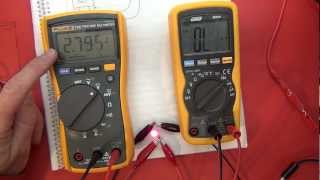
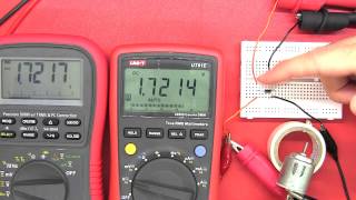
* I use some analogies to explain Ohm’s Law and what resistance is and how it affects current and voltage.
* I go through some theoretical examples and then demonstrate these in circuits.
* I show how the theory sometimes does not reflect what happens in practice.
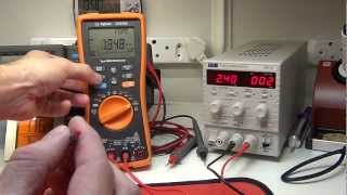
* I introduce some examples I will go through as a practical application of Ohm’s law: current shunt, voltage divider, resistor values for LED, Arduino voltmeter.
* I demonstrate my Texas Instruments TI-30XS Multiview Calculator which can make calculating formulas a little easier.
* How to work out resistance in series and parallel?
* How to work out current in a circuit?
* What is voltage / volt drop?
* What is a resistor?Electronics 101 – Ohm’s Law:
http://www.electronicstheory.com/html…Topics for future videos in this series:
* Ohms law, resistance, power, energy
* Electronic components – diodes, transistors, FETS, capacitors, digital logic gates, integrated circuits, 555 timer.
* Series and parallel circuits
* Op amps and feedback -
 6. Ohm's Law II - Applications - LED Resistors, Voltage Dividers, Current Shunts
Ohm’s law states that the electrical current (I) flowing in an circuit is proportional to the voltage (V) and inversely proportional to the resistance (R). Therefore, if the voltage is increased, the current will increase provided the resistance of the circuit does not change. Similarly, increasing the resistance of the circuit will lower the current flow if the voltage is not changed. The formula can be manipulated so that the relationship can easily be seen for all of the three variables.
In this video:
* I go through practical applications of Ohm’s law: current shunt, voltage divider, resistor values for LED, Arduino voltmeter, potentiometer.
* I demonstrate my Texas Instruments TI-30XS Multiview Calculator which can make calculating formulas a little easier.
* How to work out resistance in series and parallel?
* How to work out current in a circuit?
* What is voltage / volt drop?
* What is a resistor?
* Power calculations.
* How to calculate power in a resistor? -
 7. Analog and Digital Electronics
I chat about the effect of digital electronics vs analog electronics.
In this video:
* I go through some examples of analog and digital electronics: old cameras, cassette tapes, real to real tapes, vynal records, CD’s , compact discs, mp3 players, ipod.
* Morse code
* Understanding binary, CMOS, TTL
* Digitizing / Digitising, sound and music.
* Digital display vs analog display on a multimeter / voltmeter
* ENIAC (Electronic Numerical Integrator And Computer)
* Binary numeral system
* Sampling Frequency and Bit Resolution for Speech Signal Processing -
 8. Diodes I - Zener, Schottky, LED & Silicon Diodes
The start of digital electronics – a lead into transistors, FETs, ICs, logic gates and more…
To gain a good understanding of diodes and how they work read this wiki:
http://en.wikipedia.org/wiki/Diode#p….“In electronics, a diode is a two-terminal electronic component with an asymmetric transfer characteristic, with low (ideally zero) resistance to current flow in one direction, and high (ideally infinite) resistance in the other. A semiconductor diode, the most common type today, is a crystalline piece of semiconductor material with a p-n junction connected to two electrical terminals.
Diodes were the first semiconductor electronic devices. The discovery of crystals’ rectifying abilities was made by German physicist Ferdinand Braun in 1874. The first semiconductor diodes, called cat’s whisker diodes, developed around 1906, were made of mineral crystals such as galena. Today most diodes are made of silicon, but other
semiconductors such as germanium are sometimes used.”Items seen or mentioned in this video:
* Zener diode
* Semiconductor materials
* Light emitting diodes / LEDs
* Germanium
* Silicon
* p-n junction
* Schottky diode
* PIV – peak inverse voltage
* Full wave / have wave rectifier
* Forward bias
* Reverse bias
* Reverse breakdown
* Photodiode -
 9. Diodes II - Practical Applications
In this video I talk about the practical application and use of diodes.
We take a look at:
* The rectification of AC to DC
* Half wave bridge rectifier
* Full wave bridge rectifier
* Filter capacitor for smoothing of ripple voltage
* Voltage regulation with Zener diode.
* Advantage of Schottky / rectifier diodes
* How to build a power adapter / voltage transformer / DC adapter
* How does a Zener diode work?
* What is a capacitor?
* How to build a DC power supply? -
 10. Capacitors I
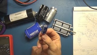
This electronics tutorial is on capacitors, how they work and some practical applications.
In this video I cover:
* What is a capacitor?
* How do capacitors work?
* Characteristics of capacitors – ESR (equivalent series resistance), ESL (equivalent series inductance), impedance at different frequencies.
* How dielectric, plates and distance account for capacity.
* RC time constant
* How to calculate the value of a capacitor using the RC time constant and an oscilloscope?
* Effect of DC and AC on a capacitor and impedance.
* Capacitors connected in series and parallel.
* Capacitors and coupling / decoupling / filtering.
* Capacitor role in digital electronics – ADC (analog to digital converters)
* Variable air capacitors
* How to choose a capacitor based on capacity, frequency, operating voltage, temperature and ESR.
* Tools to measure and troubleshoot capacitors – multimeters LCR meters, ESR meters.
* Safety and capacitors – how to safely discharge capacitors – http://www.ifixit.com/Guide/Construct…
* The future of capacitors – supercapacitors, hybrid capacitors, ultra capacitors, double layer capacitors to power electronics and cars?Practical application of capacitors used to filter ripple in an AC to DC power supply:
https://www.youtube.com/watch?v=9CoX1… -
 11. 555 Timers, PWM LED Drivers and Latched Switches I
This is also a follow-up to “A Look Inside #6 – Kelty LumaTech Cree LED Lantern”
http://youtu.be/gopsOieG7wsIn the demonstration I need to look at a leakage / quiescent current to see if it can be reduced.
Topics coved in this video:
* Some background and history on the 555 timer.
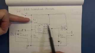
* Pin layout and description of the 555 timer DIP IC
* Explanation on how the comparator op amps work inside the 555 timer.
* Explanation on how the RS Flip Flop works and the its logic
* An explanation and demonstration of the 555 timer as a latched switch.
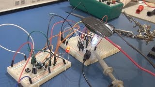
* An explanation and demonstration of the 555 timer as a PWM (pulse width modulated) LED driver / dimmer circuit.
* A look at transistors and a Darlington pair.
* A look at how we can improve the quiescent / q-point current of the circuit.
* 555 timer tutorial
* Monostable and astable multivibrator -
 12. 555 Timers, PWM LED Drivers and Latched Switches II
This is also a follow-up to “A Look Inside #6 – Kelty LumaTech Cree LED Lantern”
http://youtu.be/gopsOieG7ws
In the demonstration I need to look at a leakage / quiescent current to see if it can be reduced.Topics coved in this video:
* Some background and history on the 555 timer.
* Pin layout and description of the 555 timer DIP IC
* Explanation on how the comparator op amps work inside the 555 timer.
* Explanation on how the RS Flip Flop works and the its logic
* An explanation and demonstration of the 555 timer as a latched switch.
* An explanation and demonstration of the 555 timer as a PWM (pulse width modulated) LED driver / dimmer circuit.
* A look at transistors and a Darlington pair.
* A look at how we can improve the quiescent / q-point current of the circuit.
* 555 timer tutorial
* Monostable and astable multivibrator -
 13. 555 Timers, PWM LED Drivers and Latched Switches III
This is also a follow-up to “A Look Inside #6 – Kelty LumaTech Cree LED Lantern”
http://youtu.be/gopsOieG7ws
In the demonstration I need to look at a leakage / quiescent current to see if it can be reduced.Topics coved in this video:
* Some background and history on the 555 timer.
* Pin layout and description of the 555 timer DIP IC
* Explanation on how the comparator op amps work inside the 555 timer.
* Explanation on how the RS Flip Flop works and the its logic
* An explanation and demonstration of the 555 timer as a latched switch.
* An explanation and demonstration of the 555 timer as a PWM (pulse width modulated) LED driver / dimmer circuit.
* A look at transistors and a Darlington pair.
* A look at how we can improve the quiescent / q-point current of the circuit.
* 555 timer tutorial
* Monostable and astable multivibratorElectronic parts to get started playing with the 555 timer circuits:
http://astore.amazon.com/m0711-20?nod…CSS555 Programmable 555 Timer:
http://www.customsiliconsolutions.com…TS555 Low power single CMOS timer:
http://www.st.com/web/catalog/sense_p…An Advancement in Micro-power 555 Timers
http://blog.customsiliconsolutions.co…The 555 timer. A chip so versatile that it has been used in everything from toys to spacecraft. A chip that can act as an oscillator, a schmitt trigger, PWM driver, a siren/alarm, a light or dark detector, and much much more. It is the most popular IC of all time having been around since 1971 and now selling over 1 billion annually.
http://www.instructables.com/id/Build…
-
-
-
Topics to be covered in the series:
* What is electricity, AC (alternating current), DC (direct current).
* Resistors, Ohms law, voltage, current
* Diodes, transistors, capacitors
* IC’s (integrated circuits), logic gates
* Practical demonstrations and analogies

-
Please support the creation of new video content on MJLorton.com by turning off your ad-blocker
Thanks, Martin
-
Please support MJLorton.com and our sponsors at Programming Electronics Academy by turning off your ad-blocker
Thanks, Martin
-
Please support MJLorton.com and our sponsors at Programming Electronics Academy by turning off your ad-blocker
Thanks, Martin
-
Please support MJLorton.com and our sponsors at Tektronix by turning off your ad-blocker
Thanks, Martin
-
HDI PCB
Bittele Electronics -
Circuit Card Assembly
-
Please support MJLorton.com and our sponsors at Rheingold Heavy by turning off your ad-blocker
Thanks, Martin
-
Please support MJLorton.com and our sponsors at Contextual Electronics by turning off your ad-blocker
Thanks, Martin
-
Please support MJLorton.com and our developer Steve Kirkby by turning off your ad-blocker
Thanks, Martin