Author Topic: Electronic constant current DC load  (Read 100996 times)

MJLorton

  • Administrator
  • Hero Member
  • *****
  • Posts: 817
Re: Electronic constant current DC load
« Reply #105 on: February 17, 2013, 07:25:49 AM »
Martin I know you put a lot of work into that el-load and good job!  You mentioned in the video that with your max current limit set you did not get to use the full range of your course current adjustment control.  May I make a suggestion to look at my full schematic in this thread and see how I implemented this feature.   I think you may only need to move a couple of wires on your unit so that the max current limit comes after the course current adjustment and not before it.  This way you will get the full range of that control no mater where the max current limit is set because you are then simply scaling the control voltage to the opamp.  I haven't seen your updated diagram so I might not be correct.  Anyway great job and that was a good detailed review in the video.

Hi John,

I've just posted the basic circuit diagram. Can you please take a look and point me to where I might have made a boo boo regarding the coarse current adjustment.

Cheers,
Martin.
Play, discover, learn and enjoy! (and don't be scared to make mistakes along the way!)

SeanB

  • Administrator
  • Hero Member
  • *****
  • Posts: 1020
Re: Electronic constant current DC load
« Reply #106 on: February 17, 2013, 08:55:40 AM »
R4 should be the limit pot, with R2 being the coarse control, then R3 being the fine control. If you only have a 2k coarse control use it in the place of R2, and use a 1k ten turn preset as the limit pot in the place of R4. this means the maximum voltage available to the opamp as a reference is then going to be a voltage in the full turn range of R4.

What are the functions on the pots you have? It will also be a lot better to run the LM325 from the input side of the egulator rather than the output. It will be able to drive the mosfet better, as it then has a higher supply voltage to work with.

jwrelectro

  • Newbie
  • *
  • Posts: 36
Re: Electronic constant current DC load
« Reply #107 on: February 17, 2013, 01:35:48 PM »
Hi Martin,

I looked at your schematic and I think it should work, so I may have misinterpreted your video.  I am assuming that R4 is your fine adjust with R2 as your coarse adjust.  R3 is your maximum current limit.  Hope I got that right.  Putting two potentiometers in series for fine and coarse adjustments does work but there are some problems with linearity and total control.   For example when you have the R2 coarse pot's wiper at or near the pot's pin 3 you lose control of the fine adjustment pot R4.  With the fine pot's wiper at its pin 1 the coarse control goes to about 10% less than the total control voltage, (which is normal for this configuration).  You should also jumper pin2 and pin 3 on R4 with a wire.  If and when pots fail a loss of wiper contact is common.   With that jumper the unit would still work at a slightly lower maximum current until you replaced the pot.  Without the jumper the unit would stop working as a load. 

I assume the way you  are setting the upper current limit is to set pot R4's wiper to pin 3 and R2's wiper to pin 1 then adjust R3 for maximum allowable current of the unit.  If you are not getting the proper range from the coarse pot,  as a troubleshooting check, set the fine control's wiper to its pot pin 3 and see that you have full range over the coarse pot adjustment.  If you do not have the proper control range you probably have a wiring error in your circuit because the diagram looks all right.

There are several better ways to implement a fine/course adjustment to reduce or get rid of the problems I mentioned.  A dual ganged pot in place of the fine control is very good or you can see how chrisw957 did another method using Dave's basic circuit.  I think chrisw957 is using single turn pots.
http://www.sleepyrobot.com/wp-content/uploads/2011/05/currentload.pdf

Let me know if I can be of any further help.
« Last Edit: February 17, 2013, 06:52:38 PM by jwrelectro »

MJLorton

  • Administrator
  • Hero Member
  • *****
  • Posts: 817
Re: Electronic constant current DC load
« Reply #108 on: February 18, 2013, 04:36:06 AM »
R4 should be the limit pot, with R2 being the coarse control, then R3 being the fine control. If you only have a 2k coarse control use it in the place of R2, and use a 1k ten turn preset as the limit pot in the place of R4. this means the maximum voltage available to the opamp as a reference is then going to be a voltage in the full turn range of R4.

What are the functions on the pots you have? It will also be a lot better to run the LM325 from the input side of the egulator rather than the output. It will be able to drive the mosfet better, as it then has a higher supply voltage to work with.
Thanks Sean, I see what you are saying. I don't really want to undo this circuit at this point as it's fulfilling it's function for me at this point in time. I will pop it on a bread board to test what you have noted ready for the next one I put together.

R4 - Fine
R2 - Coarse
R3 - Limit

Cheers.
« Last Edit: February 18, 2013, 04:43:28 AM by MJLorton »
Play, discover, learn and enjoy! (and don't be scared to make mistakes along the way!)

MJLorton

  • Administrator
  • Hero Member
  • *****
  • Posts: 817
Re: Electronic constant current DC load
« Reply #109 on: February 18, 2013, 04:47:11 AM »
Hi Martin,


There are several better ways to implement a fine/course adjustment to reduce or get rid of the problems I mentioned.  A dual ganged pot in place of the fine control is very good or you can see how chrisw957 did another method using Dave's basic circuit.  I think chrisw957 is using single turn pots.
http://www.sleepyrobot.com/wp-content/uploads/2011/05/currentload.pdf

Let me know if I can be of any further help.

Hi John,

Thanks very much for your input. I had a look at Chrisw957's circuit and I will certainly test his method on a breadboard too.

Just to note on my diagram:
R4 - Fine
R2 - Coarse
R3 - Limit
 
Cheers,
Martin.
Play, discover, learn and enjoy! (and don't be scared to make mistakes along the way!)

mrbearuk

  • Newbie
  • *
  • Posts: 11
Re: Electronic constant current DC load
« Reply #110 on: July 14, 2013, 07:52:24 AM »
Q1: How do you wire the amp meter into this circuit.
Q2: How do you identify the pins on the variable resistors.

MJLorton

  • Administrator
  • Hero Member
  • *****
  • Posts: 817
Re: Electronic constant current DC load
« Reply #111 on: July 16, 2013, 10:28:08 AM »
Hello mrbearuk,

If you go back a few pages I posted a circuit diagram. The ammeter is in series with the + positive input and pin 2 of the FET. The two variable resistors are labelled with the pin outs. There should be a similar diagram / symbol on your variable resister  / 10 turn pot that corresponds with the circuit diagram.

Hope that helps.

Cheers,
Martin.
Play, discover, learn and enjoy! (and don't be scared to make mistakes along the way!)

electronicnoobblog

  • Newbie
  • *
  • Posts: 1
Re: Electronic constant current DC load
« Reply #112 on: September 28, 2013, 05:08:18 AM »
Hello,

I'm need to build DC-load with will be able to dissipate 150W of heat.

I assume following requirements:
- maximal voltage (30V)
- maximal current (5A)

My question is does someone of You create PCB for similar device ?

In posts at this topic i found some projects, but there was dedicated to smaller power and was more compact.
My device should just have controller PCB with output for transistors (no transistor or heatsink on PCB itself)

My device will use computer CPU cooler.

I'm just asking if someone create similar project and will share (to not do same job twice) if not i will create by my own and if everything will work share project.

Regards

dr_p

  • Jr. Member
  • **
  • Posts: 64
Re: Electronic constant current DC load
« Reply #113 on: September 29, 2013, 08:55:23 PM »
Any design will do. Just replace the power transistor (BJT or MOSFET) with a bigger one, or better yet, use multiple transistors. I think it's decent to keep it under 50W per TO220 and 100W per TO3 or TO247. You may also increase the value of the sense resistor to dissipate some power there.

My second dummy load handles 15A, 45V or 250W (whatever comes first). I think I can squeeze 3-400W if air cooled.
I don't have a complete schematic but I drew the power side, since that's where the magic happens. There's an error: the 0R1 5W resistors are actually 2 in parallel for each FET, so effectively 0R05 10W for each transistor.


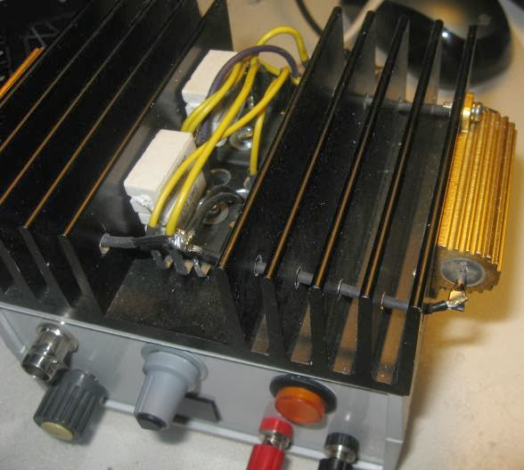
And this is how it looks like, complete with range switch (x1, x10, x100) and external modulation input (BNC):


I tested this with an ATX power supply and maxed out at 18A from the 12V rail, so in excess of 200W.
So what I'm saying is use any design, but beef up the power side, and it will work.
« Last Edit: September 29, 2013, 09:02:58 PM by dr_p »

TorqueRanger

  • Newbie
  • *
  • Posts: 22
Re: Electronic constant current DC load
« Reply #114 on: November 13, 2013, 07:21:09 AM »
How many of you have built this and would you change anything ????


I just started designing this and it's not done ..
Whats your thoughts ???
« Last Edit: November 13, 2013, 07:23:42 AM by TorqueRanger »

Paul Collins M0BSW

  • Full Member
  • ***
  • Posts: 147
Re: Electronic constant current DC load
« Reply #115 on: December 24, 2013, 03:46:28 AM »
Hi Martin, Well finally I get to make a start on the constant current load, first project for 2014, /I have two led display units which I intended to put in it, however looking on e-Bay  I see a backlit LCD unit which does DC volts and amps, with that nice pale ice blue back light, so is there any special criteria, or spec for the metering, I'll not be adding the data meter sockets on mine as I don't have or have the need for such a multimeter. This is a nice project, and it's nice to see everyone ,making one to suit their own specific needs ;)
Paul
Quietly Learning

MJLorton

  • Administrator
  • Hero Member
  • *****
  • Posts: 817
Re: Electronic constant current DC load
« Reply #116 on: January 09, 2014, 08:36:34 AM »
Hi Martin, Well finally I get to make a start on the constant current load, first project for 2014, /I have two led display units which I intended to put in it, however looking on e-Bay  I see a backlit LCD unit which does DC volts and amps, with that nice pale ice blue back light, so is there any special criteria, or spec for the metering, I'll not be adding the data meter sockets on mine as I don't have or have the need for such a multimeter. This is a nice project, and it's nice to see everyone ,making one to suit their own specific needs ;)
Paul
Hi Paul,

No , if the meter has the measurement range and resolution to match the DC load you are building it should work fine. Hope you have fun with the build.

Cheers,
Martin.
Play, discover, learn and enjoy! (and don't be scared to make mistakes along the way!)

TorqueRanger

  • Newbie
  • *
  • Posts: 22
Re: Electronic constant current DC load
« Reply #117 on: January 23, 2014, 08:31:30 AM »
Why is the main 10-turn pot 50K ???
Can't it be some other value ??

steve30

  • Full Member
  • ***
  • Posts: 155
    • Stephen Coates' Homepage
Re: Electronic constant current DC load
« Reply #118 on: January 23, 2014, 11:17:56 AM »
Why is the main 10-turn pot 50K ???
Can't it be some other value ??

Yes, its just a voltage divider, so any value ought to do the trick.

mrbearuk

  • Newbie
  • *
  • Posts: 11
Re: Electronic constant current DC load
« Reply #119 on: April 08, 2014, 05:16:18 PM »
Where can I get the case and heatsink? I use CPC to order my parts but cant find them there.
thank you.