Author Topic: Cree LED workshop lighting.  (Read 13613 times)

kibi

  • Full Member
  • ***
  • Posts: 121
Re: Cree LED workshop lighting.
« Reply #15 on: January 31, 2013, 06:40:46 PM »
So, I cobbled a reflow oven together. I found a brand new, although crappy, toaster oven in Argos for £12.99, it was the last one too! It's really small too, but perfect for most jobs. Then I got a PID controller for £11.99 and a Crydom SSR off of eBay for £3 (it was £9 for three of them). I already had a thermocouple Sorted, a reflow oven for less than £28!! Bonus.


So I have got the PCB's assembled.


I finally decided that I'd go down the Arctic Silver thermal glue route. The cases are drilled, tapped and the LED's glued down.


With any luck, I'll get on to the final assembly and installation later this week.
« Last Edit: February 19, 2015, 11:55:06 AM by kibi »

kibi

  • Full Member
  • ***
  • Posts: 121
Re: Cree LED workshop lighting.
« Reply #16 on: February 02, 2013, 06:57:25 PM »
More progress, however I did get the hole circle diameter wrong for the three dog bowl mounting holes. The diameter was 2mm over size, I don't know how I managed that, but I drilled another three 60º "out of phase" and slotted them. No big deal really, but a silly mistake to make.

Things were starting to look good.


Until.......


Now, this happened when pressure was applied to the screws whilst screwing the dog bowl to the case. The case obviously flexed and the ceramic substrate of the LED did not. The glue stuck fast even after running them for an hour prior to screwing the dog bowl in position.
I scraped the glue off the LED and tried again, this time rubbing the area with 800 grit paper, still same problem. I also did not like the thermal performance of the glue, it wasn't bad, but not good enough. It'd probably be fine with a bigger heatsink and the glue would definitely stay stuck down when applied to a rigid base.

I did come up with a ghetto solution which is working, so I may well leave it like it is.


Now what remains is to see how well the aluminium case works thermally. I'll have to leave the lamp on for a few hours to verify that.
« Last Edit: February 19, 2015, 11:56:01 AM by kibi »

SeanB

  • Administrator
  • Hero Member
  • *****
  • Posts: 1021
Re: Cree LED workshop lighting.
« Reply #17 on: February 03, 2013, 12:19:45 AM »
I get good thermal performance with metal loaded epoxy ( Pratley quickset steel) to stick heatsinks onto packages that never were intended to have one on. Sanding both surfaces lightly before application. Works well, and I have broken chips before this lets go.

kibi

  • Full Member
  • ***
  • Posts: 121
Re: Cree LED workshop lighting.
« Reply #18 on: February 03, 2013, 04:33:25 PM »
The thermal performance tests failed today. The case temperature went up to 85ºC after just 30 minutes. The die temperature was 105ºC. No good.

A re-design was needed. I was trying to avoid using bigger heatsinks as they increase the protrusion of the lamp. Also they are expensive. I do however have some good heatsinks from a previous project. Integrating these into the design meant almost an entire rework of all the mechanical parts. I had to turn the cases over because the surface that I originally had the LED mounted to now has more holes in it than a second hand dart board. Some of the existing holes would interfere with the new design.

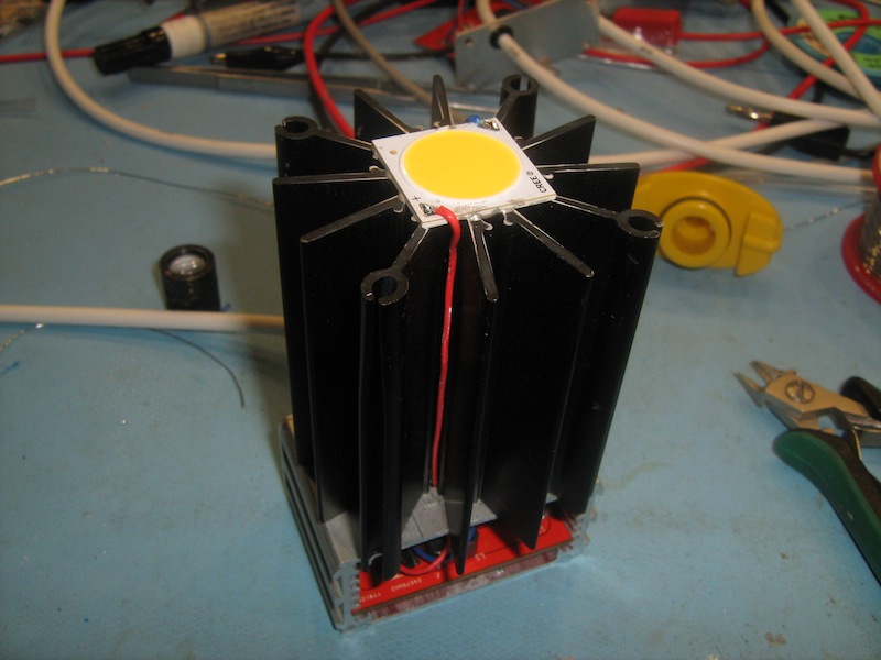
So these are the heatsinks I am now using with the LED, once again, glued on with Arctic Silver epoxy.


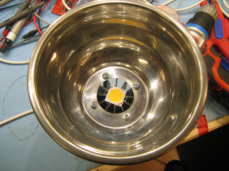
I then enlarged the hole in the centre of the dog bowl to allow for better flow of convection currents. Besides, the mounting holes are now on a much larger diameter.


Now the thermal performance is much improved. I left the lamp on for two hours and the heatsink temperature rose to 50ºC and the die reached about 85ºC. That die temperature is actually what these LED's are binned at so that was a nice coincidence. The glue is performing well now that it is bonded to a better performing heatsink.

Here are two of the lamps in position. Now I am getting 2500 lux on my worktops for less energy as opposed to the 250 lux I was getting from the fluorescent lamp. Granted, the fluorescent lamp was not in the same position, but directly below the fluorescent lamp at the same height I get 450 lux.


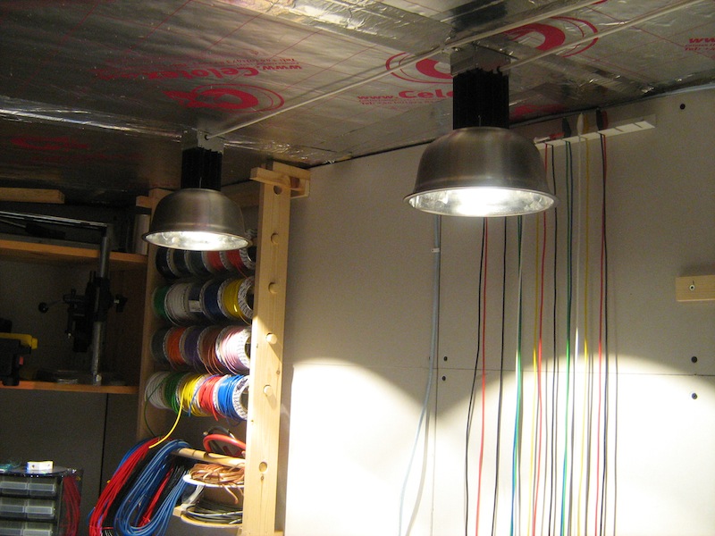
Shadows are a minor problem, about the same as you'd get from a CFL. I plan to reduce the shadows with some diffuser material.
« Last Edit: February 19, 2015, 11:56:46 AM by kibi »

MJLorton

  • Administrator
  • Hero Member
  • *****
  • Posts: 817
Re: Cree LED workshop lighting.
« Reply #19 on: February 04, 2013, 02:41:15 AM »
I love watching the way you put bits together! It's fascinating to see the path you take to eventually getting a project to work. I love seeing the odd bodge/ ghetto solution too...makes me feel a little better about my Heath Robertson hacks  :D !

I've completed my electronic DC load  and the video / forum posts will be up soon. A big thanks to you and your posts Warwick, they inspired me to consider taking on the project.

Cheers,
Martin.
Play, discover, learn and enjoy! (and don't be scared to make mistakes along the way!)

kibi

  • Full Member
  • ***
  • Posts: 121
Re: Cree LED workshop lighting.
« Reply #20 on: February 06, 2013, 06:59:33 PM »
Thanks Martin. It is all good fun and when it actually works it's quite rewarding.
I'm pleased that you have got your constant current load together. I'm glad to be of inspiration, that's the point of sharing right?

Cheers

Warwick

TerenceHarrington

  • Newbie
  • *
  • Posts: 1
Re: Cree LED workshop lighting.
« Reply #21 on: July 25, 2013, 04:08:13 AM »
I have been struggling with a silly 2x 18W fluoro tube light on the ceiling of my workshop for quite a while now. I have been wanting to upgrade it with more up to date led light.
Now, I have used Cree's CXA2011 chips before and they are fantastic, but a bit of a nuisance to drive because they operate at 42V which is quite high. Late last year Cree added some new chips to their CXA range. I went for the CXA2520, which is easier to drive at 36V and produces more light than the CXA2011 modules.
So, it was time to design a driver for the CXA2520. As I am converting my workshop power to off grid, a 12V lamp would be ideal so that I don't have to convert to 240V and then down again to drive the lamp.
Micrel provided the answer for me in the form of their MIC3223. It was cheap, operates from IIRC 5V -20V input, provides programmable constant current up to 1A and can boost up to 37V MAX. Another bonus is that the switch is built in to the MIC3223, so no silly external MOSFETs are required. It switches at 1MHz. It even accommodates PWM dimming control, but you need an external MOSFET for that function of course, but no big deal.
All you need is an inductor, a snubber, diode, a few resistors for programming constant current, high voltage cutoff point and a few capacitors for decoupling.
All of the external components will fit within 1206 packages, so a nice easy, small single sided board layout can be used.
I designed my circuit pretty close to that described in Micrel's datasheet.


I designed the board in Eagle, but I have made it larger that it needs to be because the larger dimension fits nicely inside the case that I intend to use.
I soldered it all on by hand because my PID oven project has ground to s shuddering halt.


This is the LED on a temporary heatsink for now.


At first the circuit powered up and worked straight away - which was a bit disappointing. However, the fun began when the LED started flashing on and off at 1 or 2 second intervals.
After much debugging, I figured that the bottom pad, which is also pin 17 or EXP on the diagram did not flow. I figured this by the higher than expected temperature of the MIC3223.
I gave the board a quick whirl in my trusty frying pan and then everything worked as it should. The MIC3223's temperature dropped too.

At 12V we are consuming 1.7ish Amps. 20.4W.
On the output, we are running at about 35.5V, 545mA. 19.34W
This makes the circuit about 94% efficient. :)

The LED current remains constant with input voltages as low as 5V and I've taken it up to 18V with no problems. MAX Vin is 20V. With such low input voltages, I could even make a bicycle light with two Lithium batteries :) Of course the current increases, but there you go.

The LED can be driven harder than I am, but I'm not so sure it's necessary. The current tube light measures 100 lux from the ceiling with the light meter on the floor. The single LED measures 160 lux and 100 lux if it's 1 metre off axis from the light meter. I'll be making four such lights.

Next thing is to do the mechanical bits. I'll update when it's done.


Thanks man that is just awesome information.. I would love to work on similar project and share my experience..
« Last Edit: July 26, 2013, 01:00:12 PM by TerenceHarrington »