Hello everyone.
A few months ago I posted about my off grid workshop. The batteries turned out to be a failure, so I had to start from scratch. I have saved up some money and bought some more components. So here we go for the second take.
A shopping list had to be devised. One important component is the charge controller. I'd heard good things about Outback products, but then discovered there was a better alternative. Midnite Solar make a Classic charge controller which is a lot more powerful and has pretty much all the features you'd want built in. Cool, I then spent many man hours searching for a better charge controller than the Classic, but failed.
The charge controller needs to be well built to ensure reliability and it needs to be future proof. The Classic does this. I'll max it out at 1KW on my 12V system, but with higher voltage battery banks in the future I'll get close to 5KW out of it. What more do I need from a charge controller?
I am on a 12V system because I have a 12V Victron inverter that served it's previous life in an ambulance. I also have several other 12V loads, so 12V works for me at the moment.
So, lets get started with the install.
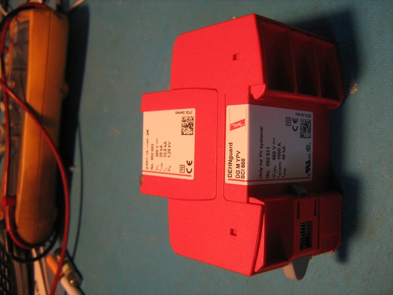
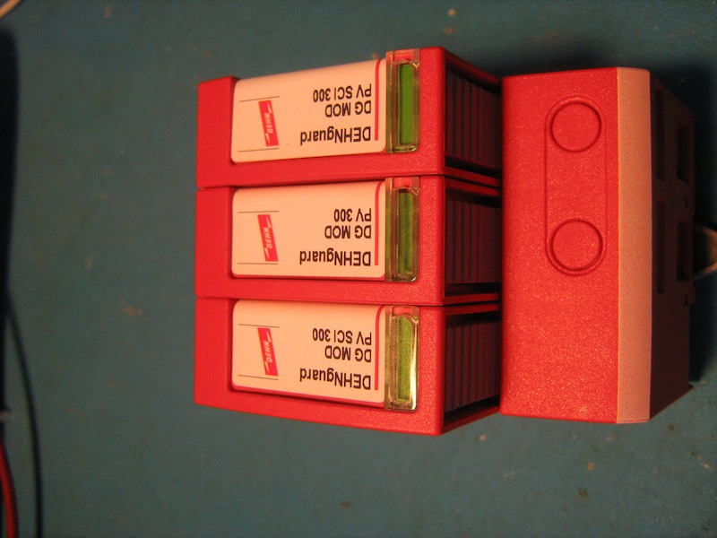
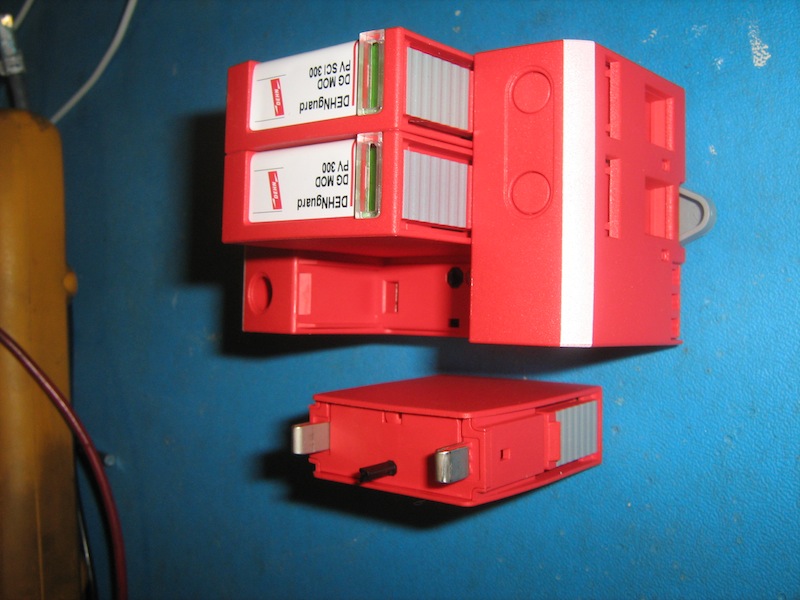
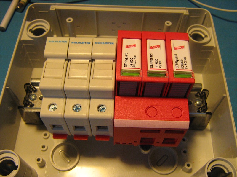
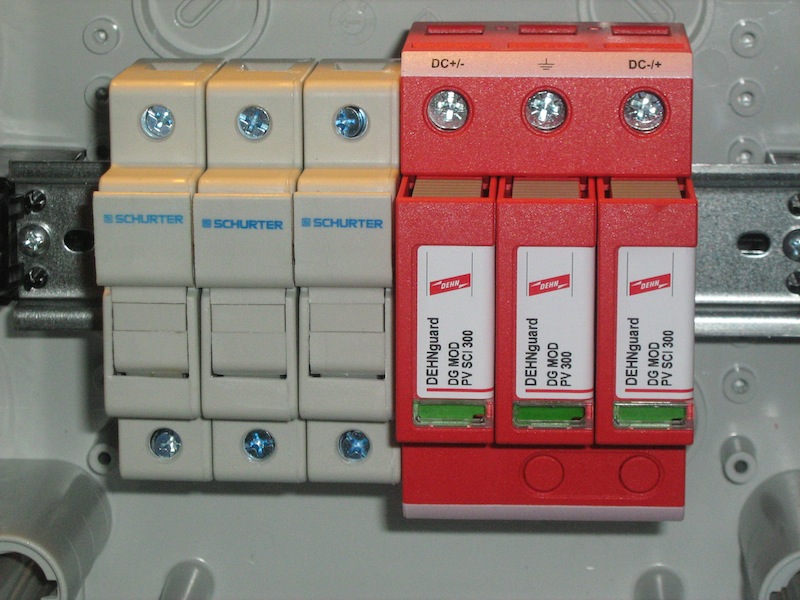
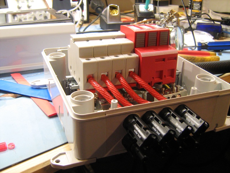
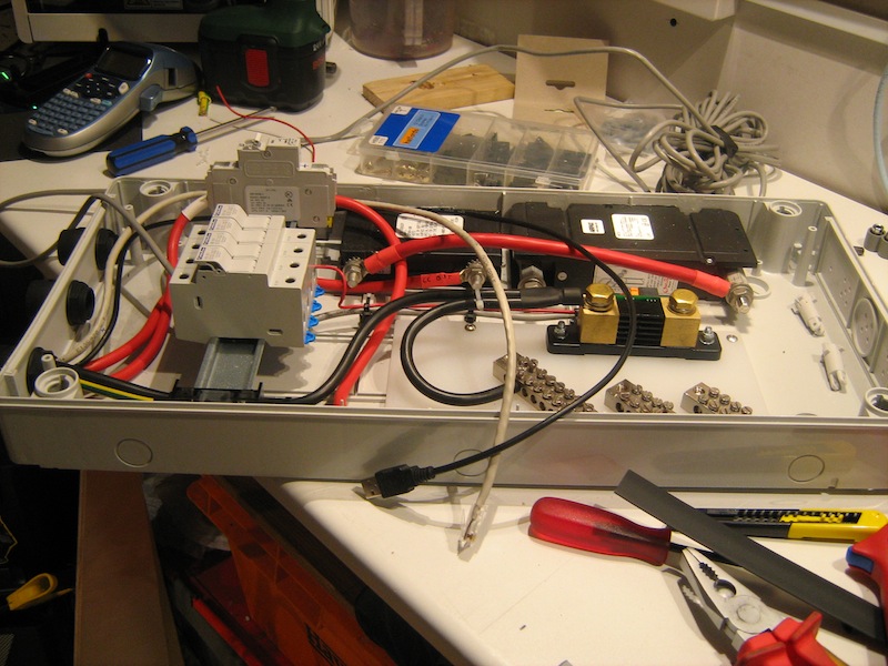
First in line is a combiner box with surge protection. I went for a Dehn PV designated SPD with replaceable modules and remote status contacts.
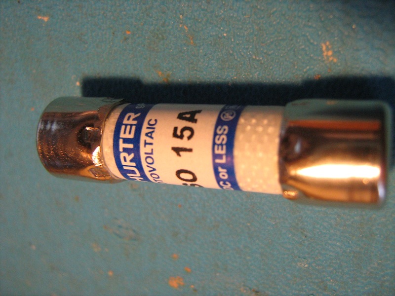
The fuse holders are 1KV rated with 1KV rated fuses at 15A. The 1KV fuses are expensive. They cost as much as fuses in a good multimeter, which should also be 1KV fuses, but I deem them necessary.
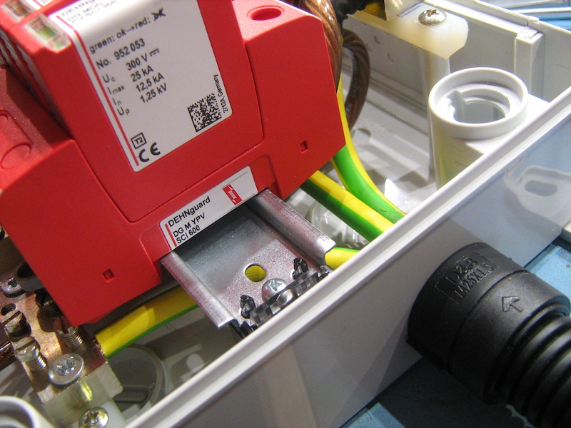
The Dehn SPD.
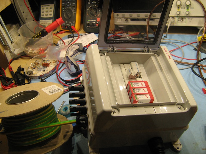
Fuses
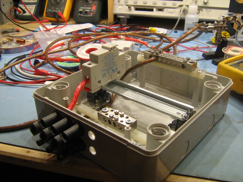
I have found an inexpensive IP65 rated DIN rail box made by ABB to mount all of the components of the combiner into.
Now, it's time to connect everything up.
I had some spare cable lying around. It's the type that a rude boy might use to cobble his sound system together with in his car. It's over rated, but it'll work well and it's free.
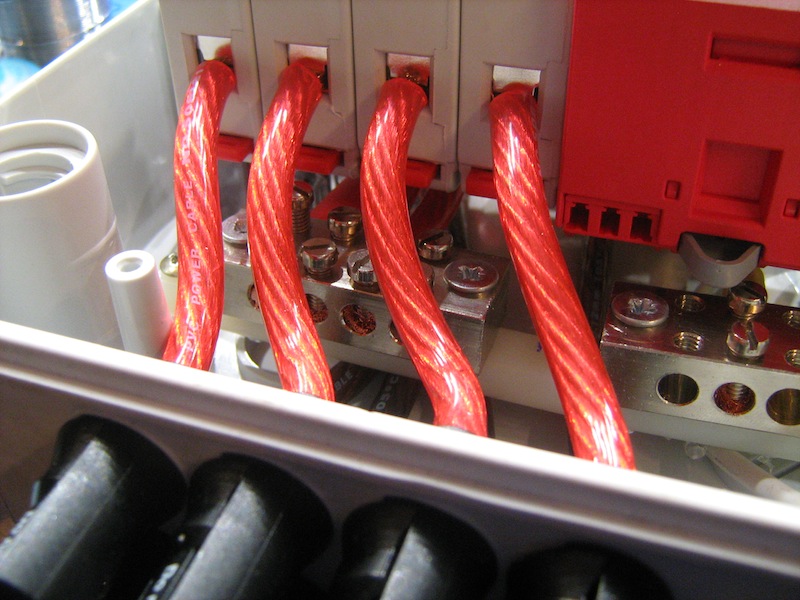
I wasn't prepared to buy more cable for the run from the combiner to the breaker box when I already had plenty of 25mm² earth cable, so I marked the ends and used that instead.
Now we have build a DC disconnect box. Again, ABB came through with a good sized box. It's IP65 rating is not necessary as it will be inside, but it's perfect for the job.
Midnite make a really nice DC disconnect box, but it does not have enough DIN ways on a single side to meet my requirements.
This box lives inside and contains some staunch DC breakers. You must NEVER use AC rated breakers on DC systems. AC breakers do not have the arc extinguishing abilities that DC breakers do. AC rated breakers from your local Toolstation are remarkably cheaper, but they will make a fire, when opened, quicker that you can light your BBQ.
I have a 250A breaker for the inverter, a 100A breaker on the output of the Classic and a 63A breaker to the PV input of the Classic. All of these breaker are disconnecting breakers which makes it convenient for me if I need to switch certain circuits off manually.
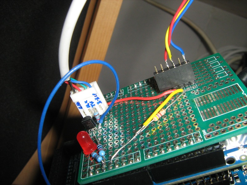
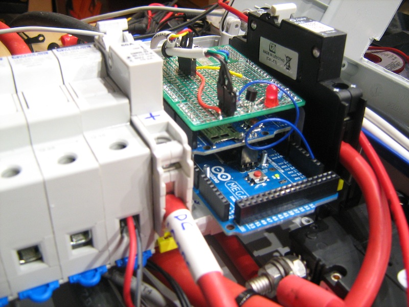
The disconnect box also houses a 60A DC breaker which is the main breaker for all of my DC loads. Downstream of this breaker are six 600V fuses for each of the DC circuits which include home-brew LED lighting, computer, and security systems. There is also a circuit for the Victron BMV-600 battery monitor and an Arduido MEGA which grabs data out of the BMV-600 and reads some DS18B20 temperature sensors.
Arduino with ethernet board for posting to Cosm and a top PCB for connections.
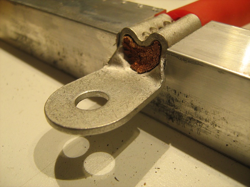
I don't have a high capacity crimping tool for the 70mm² cables, so I cut a pocket out of a piece of aluminium stock on the mill. The pocket holds the connector snugly. I then proceeded to beat all seven shades out of the top of the connector with a hammer and nail punch. That connector is not coming off.
Things are starting to come together. Power cabling is in as well as the data cabling.
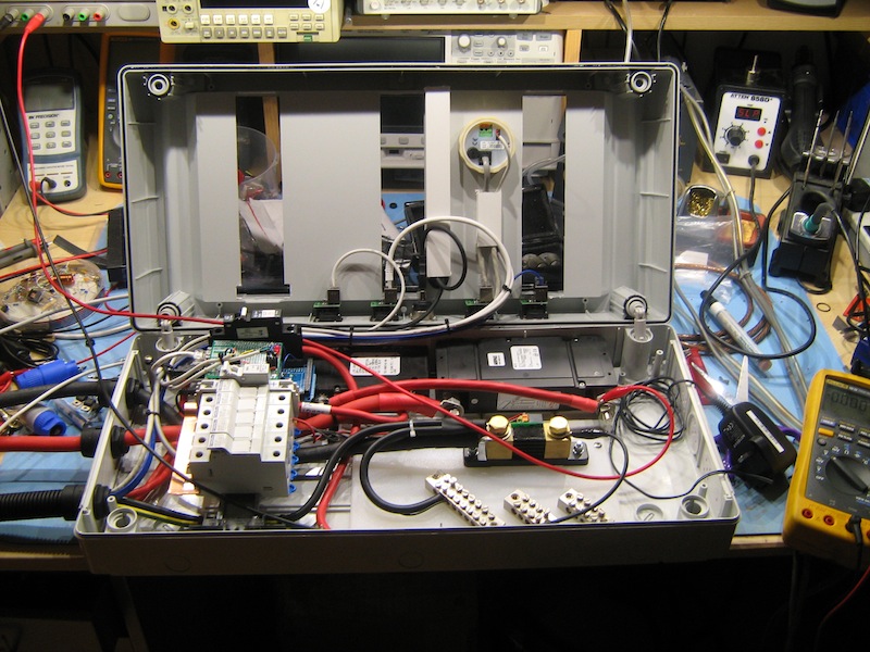
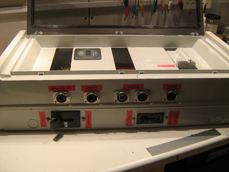
All of the breakers are labelled. All of the data connections are presented on the side via panel mounted Neutrik connectors and labelled accordingly.
Now that the DC disconnect box is ready, we need to install it and the other bits of equipment.
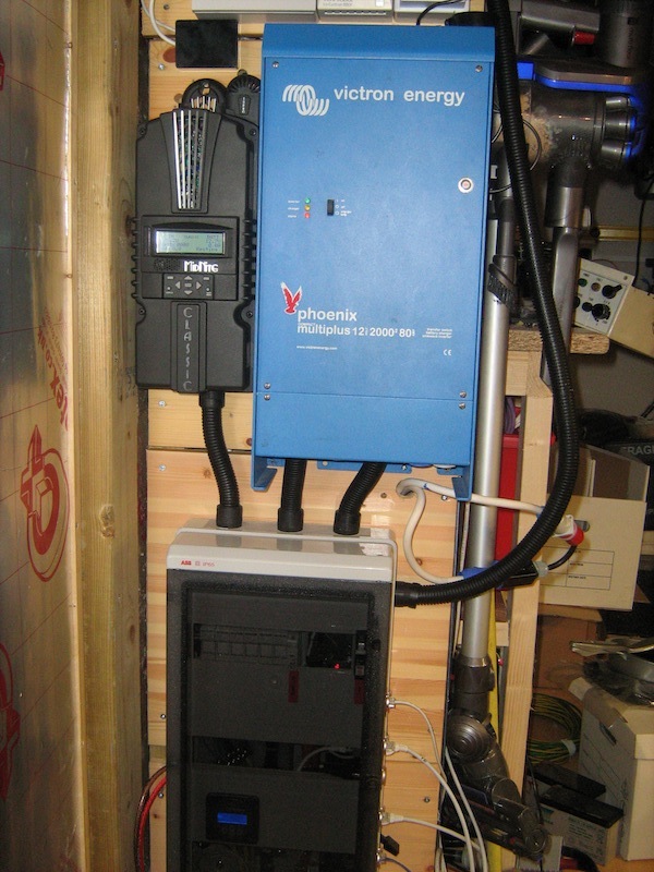
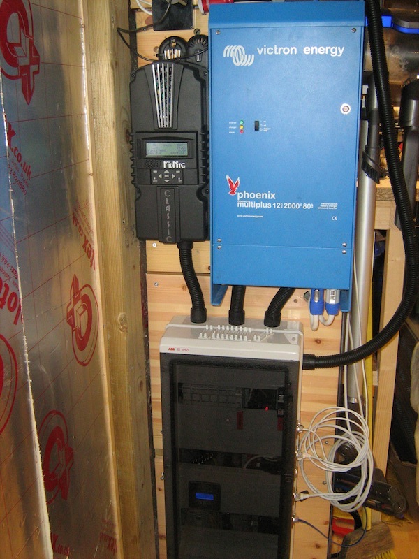
The inverter is mounted above the DC disconnect box. The DC disconnect box now assumes it's vertical position which is the position that the big DC breakers need to be mounted in, to avoid fires.
DC disconnect box mounted and the PV inlet cables connected.
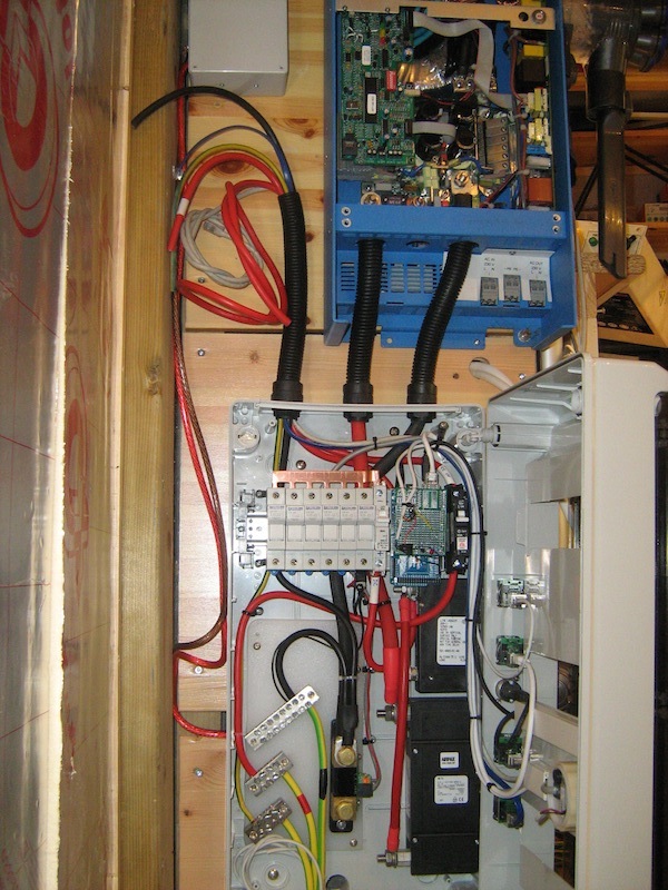
Inverter DC inlet cables connected.
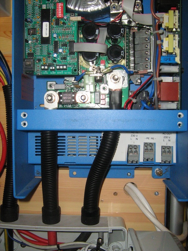
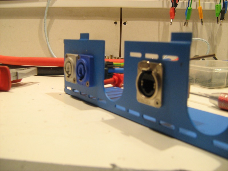
I have modified the bottom tray of the inverter to accommodate Neutrik Powercon mains in and out connectors to aid in easier removal of the cabling if necessary. I have also included an RJ45 connector in order to present the RS485 in a neater fashion.
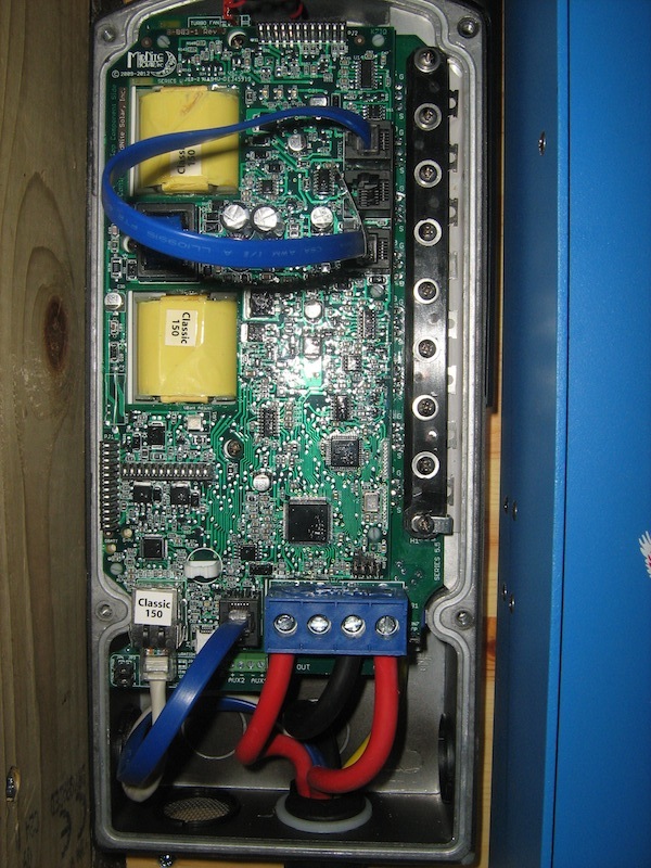
Next up is the Classic charge controller. It's actually made in America, so it's made of metal and the PCB's are conformally coated, you don't see that very often these days!
The Classic is mounted and all connections made into it.
Everything is mounted, closed up and ready for testing.
Now, I did try an experiment a few months ago with some old UPS batteries that I found in a bin. All 96 5Ah batteries were wired up in parallel to make a nice big 12V pack. Managing 96 12V 5Ah batteries in parallel proved to be a bit of a nightmare, so the "Time Bomb" had to go. It's not all bad, I have a use for these packs. Stay tuned for details later on.
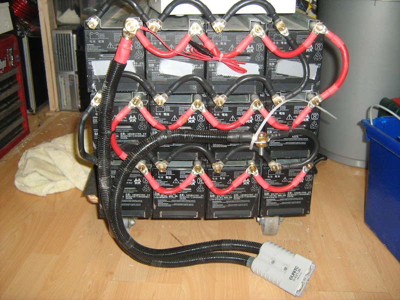
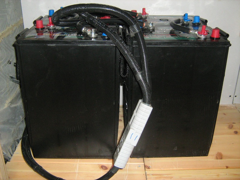
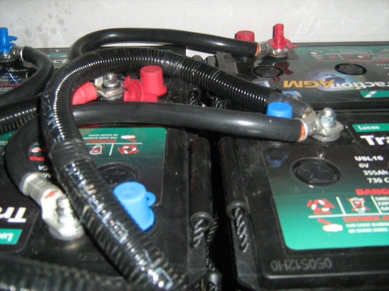
The original battery bank has now been replaced with four Lucas 355Ah 6V batteries in a 2S, 2P configuration. Two parallel banks is a lot easier on the heart.
This bank now gives me twice the capacity of the old one.
After the big switch-on, everyone is happy. Power is flowing, data is flowing.
The inverter is currently keeping an eye on the batteries until I get the PV's installed. I don't have time to do it right now, but I'll report on further progress.
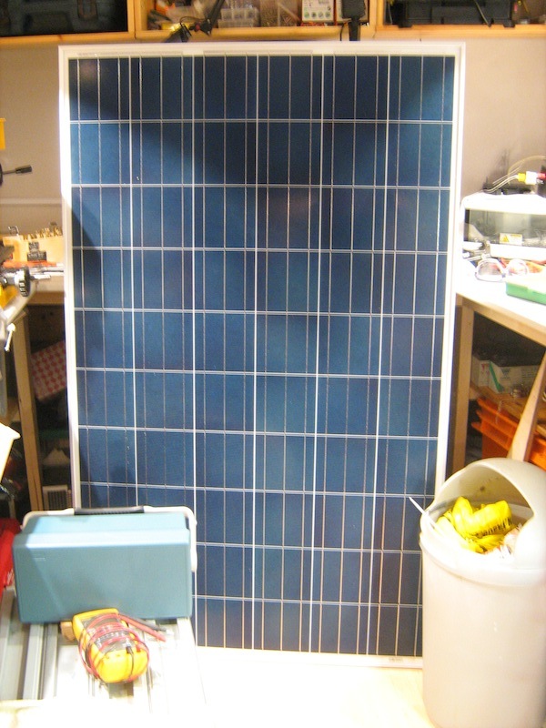
Here are four Renesola 250W poly panels awaiting installation.