Author Topic: Tim Nolan's Arduino MPPT - now with LCD  (Read 126809 times)

smaBonham

  • Newbie
  • *
  • Posts: 4
Re: Tim Nolan's Arduino MPPT - now with LCD
« Reply #30 on: August 31, 2013, 04:36:19 PM »
This is exactly what I would like to build, but it currently exceeds my ability to do so. Are there any videos or tutorials that take you through a project like this, step by step, explaining the circuit, the principals and the code for the arduino?

studioeng

  • Newbie
  • *
  • Posts: 1
Re: Tim Nolan's Arduino MPPT - now with LCD
« Reply #31 on: September 09, 2013, 10:04:05 AM »
I read your initial posts and you mentioned about including networking capability, but would be short of I/O pins; have you looked into controlling the LCD via a shift register 74HC595 etc, which would only require 3 pins, possibly freeing up others for networking.

bricofoy

  • Newbie
  • *
  • Posts: 3
Re: Tim Nolan's Arduino MPPT - now with LCD
« Reply #32 on: September 18, 2013, 11:26:45 AM »
Hi everyone.

I need to use 3 PV panels to power a small electric water heater. I know, this will give a very bad efficiency compared to regular solar water heater, but in that case I really need to do it this way.

So if I directly connect my PV panels output to the heating resistor, I will get a very bad efficiency most of the time. So I need to place some sort of mppt or impedance  converter between panels and resistor.

I think with this device I can get something working. But my problem is I have 3 120Wp panels in series, so I get nearly 45V/8A at mpp, and 60Voc. So this circuit need some adjustment to allow working with higher voltages, especially because I must power the mcu from the solar panels, as there is no battery.

So do you guys have some links to somewhere that can explain how to calculate the dc/dc converter elements to change the working voltage ? I have absolutely no idea how to calculate the inductance and capacitors for the converter.

Do you think I need another converter to produce the 5v ? or can I do it with some sort of linear regulation ?

thanks
« Last Edit: September 18, 2013, 01:36:41 PM by bricofoy »

SeanB

  • Administrator
  • Hero Member
  • *****
  • Posts: 1019
Re: Tim Nolan's Arduino MPPT - now with LCD
« Reply #33 on: September 18, 2013, 01:51:01 PM »
Best is not to use a MPPT unit, but just run the heater direct. Use a heater rated for about half the open circuit voltage ( or a little below the MPPT voltage) and rated to draw the nominal power of the panels. It will be a little overdriven during the peak part, but for a simple resistive heater this is fine. For you this will mean a heater of around 36V and rated at 360W. Simpler will be to use a series connected set of 12V 120W heaters if possible, or else you will have to contact a heater element supplier and get one made to fit as a custom unit.

Overdriving the heater is not going to be much of a problem so long as you do not do so while it is dry, as the water moderates the temperature. I have some heater elements in a machine which does a fast warm up by running them for 3 minutes at double the supply voltage ( so 4 times the power) and they generally last many years in this application.

bricofoy

  • Newbie
  • *
  • Posts: 3
Re: Tim Nolan's Arduino MPPT - now with LCD
« Reply #34 on: September 19, 2013, 03:40:24 AM »
Hi

thanks for your answer.

This will work ok for the most sunny hours of the day. But what about the sunrise and sunset ? And what about cloudy days ? I gess the working point will be far from mpp point of the panels in such a situation.

The other problem I have is I can't change the resistor in the heater. I think I need to explain a bit what I need to do : in a house we build, there is a solar water heater with the storage tank located near bathrooms, and PV panels covering all the roof.
That's ok for bathrooms, because hot water will arrive quickly.
But not for the kitchen, wich is located quite far from the hot water tank. So we plan to place a small (30 liters) water heater just in the kitchen, feeded by the hot water line, to have a little storage of hot water inside the kitchen and get hot water quickly when demanding for it.
For legal reason here in france, it is complicated for individual people to connect more than 3kWp PV to the mains, so as we want all the roof surface covered with PV panels for esthetical reasons, we get 3 panels we can't connect to the inverter because we will override the 3kWp legal limit.

So the idea here is to use these 3 panels to power the kitchen's water heater when possible. But that implies when there is no sun I also need to connect this heater to mains, so for this reason I must keep the 600W 220V heating element. And there is no way to put 2 different resistors together in the device.
Connecting this 600W element to 360Wp panel will give me a working point quite far from mpp, and give me a very bad efficiency. That's why I think with some sort of mpp device between panels and resistor I can transfer my 300W available power to the resistor.

kaizer98

  • Newbie
  • *
  • Posts: 2
Re: Tim Nolan's Arduino MPPT - now with LCD
« Reply #35 on: October 15, 2013, 11:46:09 AM »
Hi kibi,

Thanks a lot again, for this great project!

Cheers,
Yikai

MJLorton

  • Administrator
  • Hero Member
  • *****
  • Posts: 817
Re: Tim Nolan's Arduino MPPT - now with LCD
« Reply #36 on: October 21, 2013, 12:35:46 PM »
For those interested this gent (Julian Ilett) has done an interesting project too:

Arduino MPPT Solar Charge Controller #17 - Buck Converter Efficiency
http://youtu.be/c0mE4nS0low
Play, discover, learn and enjoy! (and don't be scared to make mistakes along the way!)

kaizer98

  • Newbie
  • *
  • Posts: 2
Re: Tim Nolan's Arduino MPPT - now with LCD
« Reply #37 on: November 09, 2013, 11:18:46 AM »
Thanks Mr Martin for introducing another project on MPPT.
I wish someone could help me out on this. This is quoted from: http://www.timnolan.com/index.php?page=arduino-ppt-solar-charger.

"On the graph (Fig. 5), the line labeled “PPT On” shows the watts generated by the solar panels when the PPT was running the hill climbing algorithm. Every 10 seconds the PPT set the DC/DC converter to a 1/1 ratio simulating a direct connection between the solar panel and the battery. The watts are measured and plotted on the graph as “PPT Off” showing the power that would be generated by the solar panel if it was directly connected to battery. The difference in watts between “PPT On” and “PPT Off” is the power gained by using the PPT. In this case the battery is being charged with about 20% more power when the PPT is on."

I want to do this, but I do not know how to edit his code to achieve this. I really wish someone could help me out on this, and really thank you to anyone who is willing to help!

Cheers,
Yikai
« Last Edit: November 09, 2013, 11:20:33 AM by kaizer98 »

jam770

  • Newbie
  • *
  • Posts: 2
Re: Tim Nolan's Arduino MPPT - now with LCD
« Reply #38 on: January 11, 2014, 01:43:38 PM »
OK, so I have made some more progress with this project.
The 20x4 display arrived and I have got it to display more useful information in a more easy to read manner.


I'm quite pleased with the way it works now.
I am now busy designing the PCB, well I have designed it, but looking at it, I've decided its crap. I'm going to have to start again, but that's just the way these things go.
Idea's of networking the charger have popped into my head, but I'm not sure if I have enough I/O's left on the MEGA328. It would be cool to have remote monitoring and data logging ability.

Hi

I am too working with tim nolan design, in order to use the least data lines i am using the shift reg library. this limits to 3 i/o lines and i can use the rest for other uses.

mega-hz

  • Newbie
  • *
  • Posts: 14
Re: Tim Nolan's Arduino MPPT - now with LCD
« Reply #39 on: July 13, 2014, 05:03:55 AM »
Hi,

a week ago i  found Tim Nolans Website and build the MPPT for my 235W Solarpanel.
It works great, i put a RF24 Radio to send the Data to my Datalogger.
Works fine.
The idea with the LCD is great, that feature will be implementated soon.

But now something strange...:

Yesterday i had a look at Tim Nolans DC-AC Inverter..
Today all of Tims Website is down!
A week ago i send a mail to him but did get no reply...
I have a strange feeling something happend to Tim. :-[
Does anyone know something?

Regards,
Wolfram.

SeanB

  • Administrator
  • Hero Member
  • *****
  • Posts: 1019
Re: Tim Nolan's Arduino MPPT - now with LCD
« Reply #40 on: July 13, 2014, 11:42:06 AM »
Do not know, but luckily Archive.org has a snapshot from 9 June that is still good.

http://web.archive.org/web/20140626064134/http://www.timnolan.com/index.php?page=arduino-ppt-solar-charger


mega-hz

  • Newbie
  • *
  • Posts: 14
Re: Tim Nolan's Arduino MPPT - now with LCD
« Reply #41 on: July 15, 2014, 02:48:41 AM »
thank you, thats nice that they keep a copy of his site!

@jam770:
how is your project going?
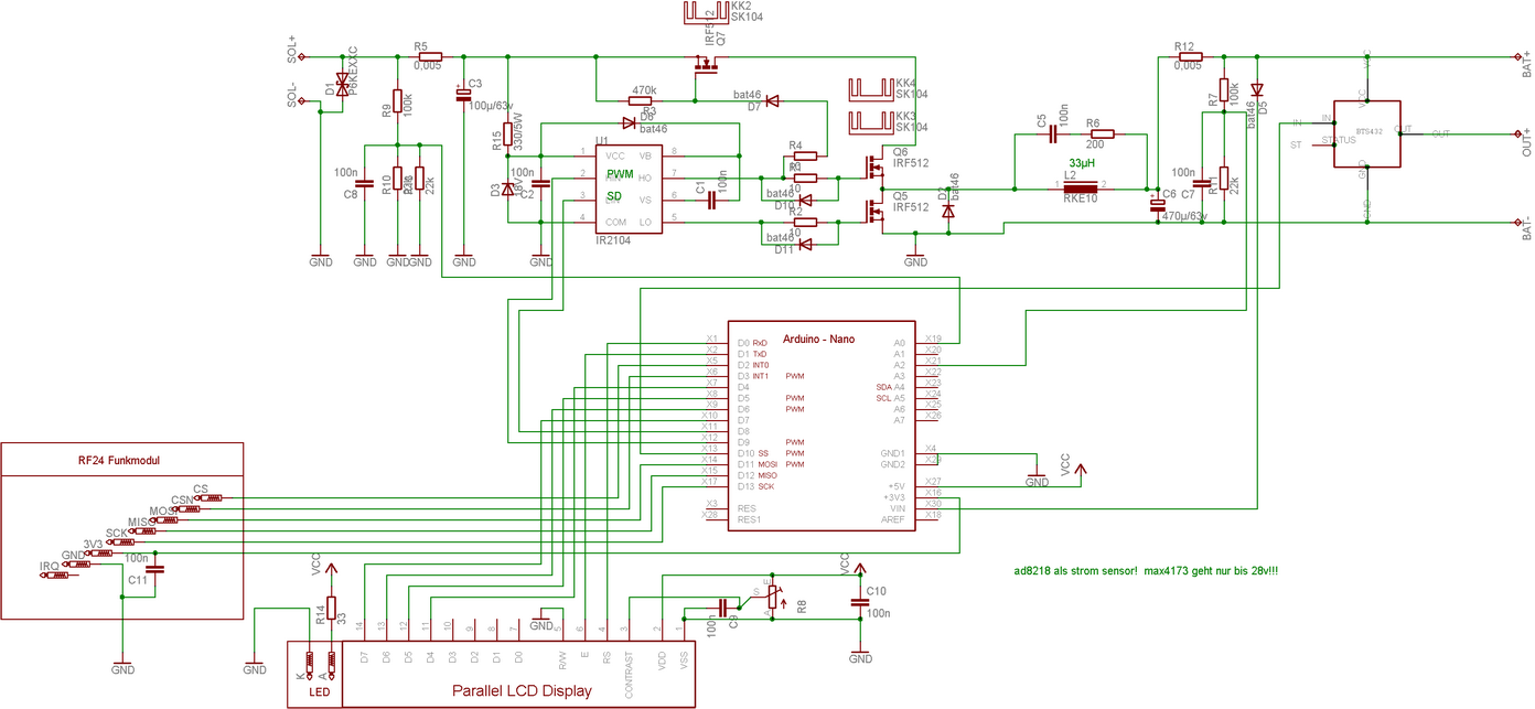
I started a new pcb for this mppt charger, it includes Tim Nolans Arduino Code with your LCD-routines,
i removed the serial part and added a RF24 wireless data communication,
added Battery_amp and watts and added a voltage-controlled output switch wich turns off the load when battery goes under BAT_MIN (11V) and reactivate output at 12.5V.
The Output-switch is made of 10x BTS432 in paralell.
I also changed the voltage-divider for the solar-panel, so you can use bigger panels with higher voltage.
My panel make 44V and 38V without load.
Because the MAX4173 doesnt work with 50V i changed it to a AD8218 current-sensor which can handle up to 80V.
These Current sensors are not yet included in the eagle files..
here some files:


note, the current sensors are not yet includet!

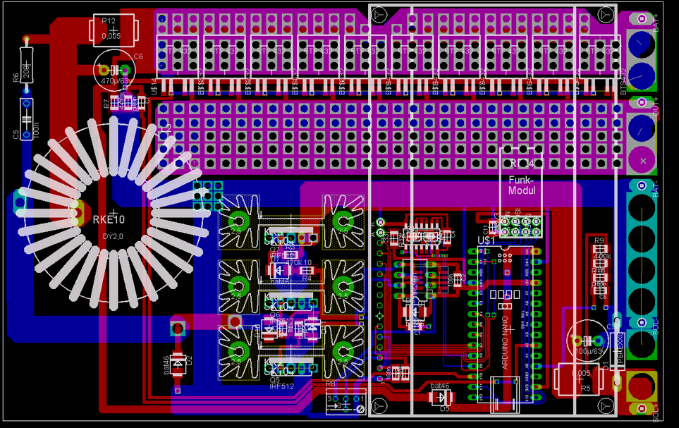
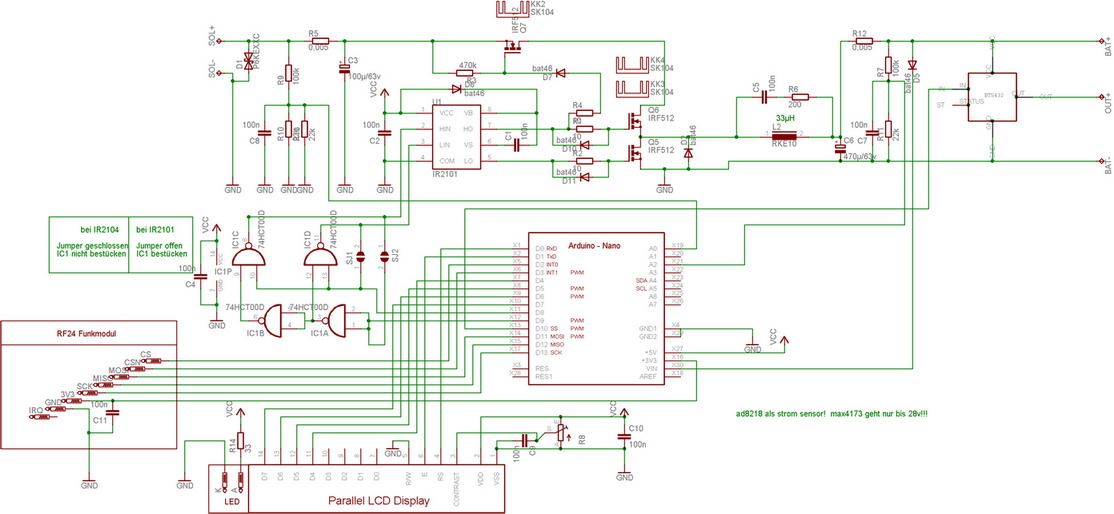
here the eagle-files:
http://www.mega-hz.de/solar_mppt_charger/arduino_solarcharger.brd
http://www.mega-hz.de/solar_mppt_charger/arduino_solarcharger.sch

and the Arduino Code:
http://www.mega-hz.de/solar_mppt_charger/solar_regler_wf.ino

Note the pin numbers for the lcd have changed!
Another change is the use for either IR2104 or IR2101 (those i have laying in the drwaer), thats why the 74HCT00 is there...
If you use the IR2104 dont use the 74HCT00 and close the jumpers!
Also ther is a place for either the DIP-8 or the SO8 SMD Version.


any suggestions?

going on with the tests on the breadboard..

EDIT:
removed 74HCT00 and the option for a IR2101... the signals for the pwm are not as they should. Just use the IR2104.

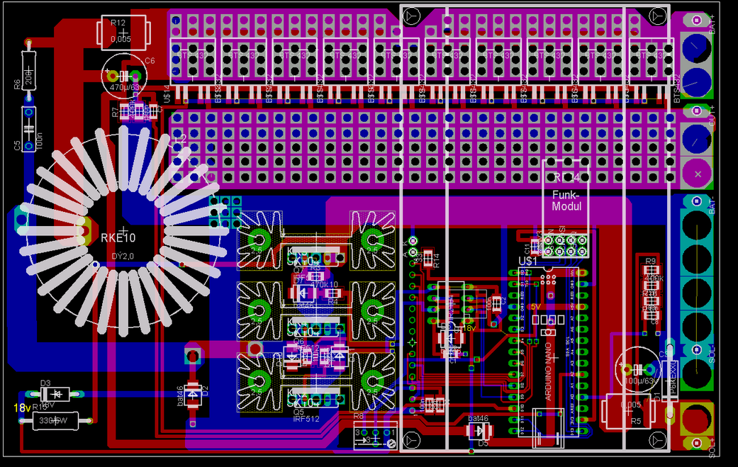
Found an error: the VCC of the IR2104 was on +5V, that doesnt work, it must be 10-20V.
Added a 330R and a 18V Zenerdiode for the supply of the IR2104. (Hope this won't get to hot when the Solar gives 40V...)


Wolfram

EDIT:
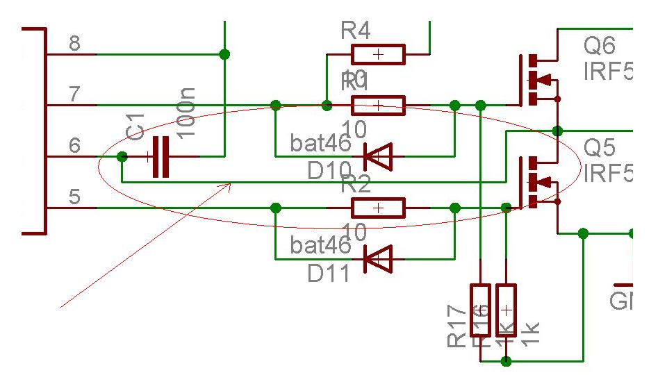
another error found!
The connection between ir2104-pin6 to the mosfet-outputs was missing..
also added 2x 1k resistors for quicker and safer turn-off of the mosfets.


« Last Edit: July 16, 2014, 03:07:27 PM by mega-hz »

mega-hz

  • Newbie
  • *
  • Posts: 14
Re: Tim Nolan's Arduino MPPT - now with LCD
« Reply #42 on: July 17, 2014, 04:33:12 PM »
the schematics and the layout are updatet now, i think its ready for itead-studio...  :)


also 3 current sensor are includet now! (AD8217)

What do you say to this? (Or isn't anybody reading this threat??)
« Last Edit: July 17, 2014, 04:43:32 PM by mega-hz »

mega-hz

  • Newbie
  • *
  • Posts: 14
Re: Tim Nolan's Arduino MPPT - now with LCD
« Reply #43 on: July 20, 2014, 03:51:39 AM »
5 prototype pcbs are ordered now.

mjeanne

  • Newbie
  • *
  • Posts: 6
Re: Tim Nolan's Arduino MPPT - now with LCD
« Reply #44 on: July 20, 2014, 04:28:41 AM »
good job

I'm looking for documentation for building my own solar mpp tracker.
I've some questions:

- what is your power source for the nano ? I'm looking at a LM2596 which could convert from 4 - 40V to 5V @3A, so I can power all chip (µC+display) from the battery, and I got 5V for charging my phone. Do you think it can be ok to power from the battery ?
- why do you use AD827 which require a resistor, instead of something like acs712 which doesn't affect the circuit ?
- do you have a better resolution of your schematics and can I use it for my testing ?

(sorry if bad english, I'm french)