Hi
I have been meaning to build one of these for a while. I finally got around to it this week.
I have mostly used parts that I already had in stock. The only things I bought specifically for this project were the 10 turn pot, heatsink and meter.
The 10 turn pot is very expensive, but necessary and makes the device so much simpler to use, so worth it in my opinion.
The circuit is based on Dave's design on Youtube alongside his "World's simplest soft latching power switch". The soft latching switch is included mainly because I think it's cool and is made with "jellybean" components that anyone who owns a soldering iron should have in stock

Dave's dummy load video :
http://www.youtube.com/watch?v=8xX2SVcItOADave's "World's Simplest Soft Latching Power Switch Circuit" video :
http://www.youtube.com/watch?v=Foc9R0dC2iIOne feature I really wanted to include was the ability to set the load value prior to connecting the load. It's very difficult to judge where you are with a 10 turn pot. You could just wind the pot down to 0 and then work up from there, but it's a bit cumbersome I think.
I found an old junk PCB with a Hamlin reed relay on it. This particular relay has C/O contacts and has a 5v coil with the flyback diode built in. I consumes 25mA, but this is on momentarily, so not a problem for my battery powered design. The relay switches the meter between "set" and "read" values via a momentary push button on the front of the case.
A last minute feature I added was a pair of 2mm jacks to connect a DMM to if you want to monitor the voltage of your load at the same time. Not strictly necessary, but it offers rather a convenient place to connect standard 2mm meter leads.
I thought about including maximum power protection, but with the current limited at 2.5A there will be no problems as long as you don't exceed 50V.
The MOSFET's will blow up at 60V anyway, so you have got a whole set of other problems if you do exceed the maximum voltage. The power is well within the limits of the MOSFET pair if you stay below 50V.
I suppose a maximum voltage lockout could be employed, but I couldn't be bothered and I just wanted to get this thing done. I can't imagine myself going beyond ~25v anyway, so there is no problem for me.
I have based the circuit around the Texas TLV2374 quad rail-to-rail op-amp that I have in my parts bin. It's old, but it's good. I even managed to use all four op-amps in my design.
The actual layout of the circuit and the use of strip board could be improved upon especially in an amplifier such as this with high currents involved, but it worked in the end.

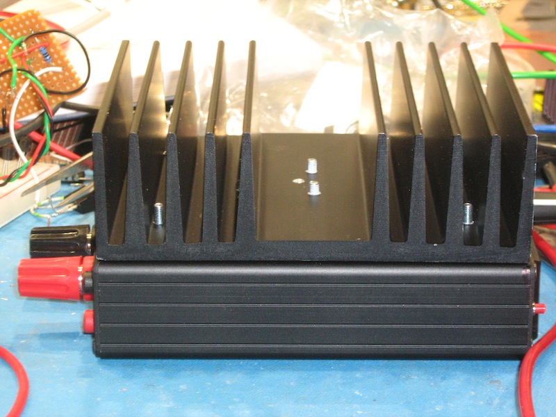
So, first off, design the case. It's a Hammond case that I bought for another project, but found it to be unsuitable in the end, so I used it for this project.
Here all the apertures are cut and holes drilled and threads tapped as necessary. A tungsten carbide drill bit snapped in one of the holes, so it's there to stay, (me being a dumb-ass).

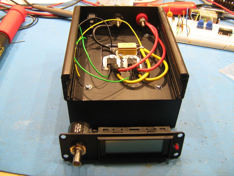
Power resistor (10W) and a pair of FQP50N06L MOSFET's are bolted down and wired up. The FQP50N06L is one of my personal favourites.
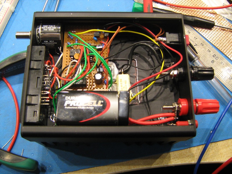
The "wiring" is complete and ready to be tested.
I then performed some testing and it didn't go too well. It worked, but it oscillated like a good 'un, 750KHz to be precise! Not too surprising really, with all those long wires and a badly laid out board, but short of sitting down and designing and fabricating a board, I cured the oscillations with a 10nF across + and - of the comparator section. It then settled down and worked well.
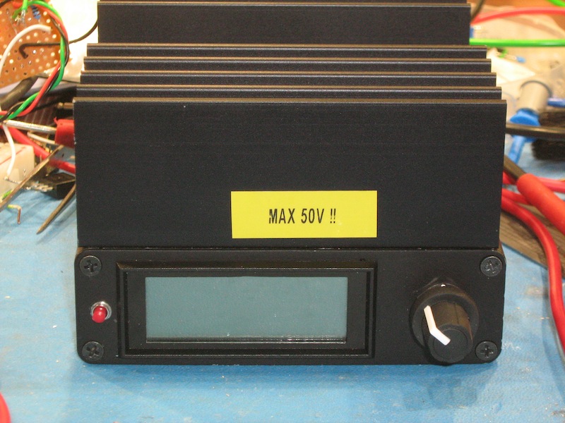
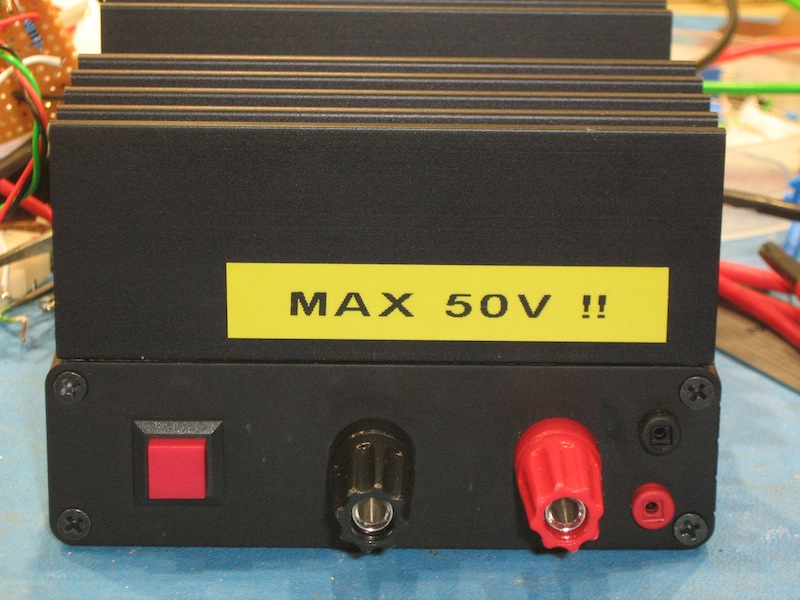
Here is the completed project.
On the left front of the case is the set/read button. Without a load connected, you hold down the button and dial in your preferred load current.
On the rear are the load connections, 2mm sockets for meter leads and the power button.
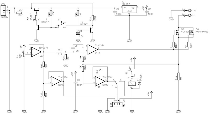
I have included the circuit diagram that I drew if anyone is interested.